Case 2
- Introduction
- Causes of Defects
- Good Practices
- Standards
- Maintenance and Diagnostics
- Remedial
- Similar Cases
- References
Good Practices
Pipe Penetration
Design
A well-planned layout and detailed working drawing should be provided to reduce chances of hacking
or porous infill of cold joints in accordance with BS EN 12056-2 or equivalent. Pipe sleeve with a puddle flange should be used to seal around the outside of pipes that are recommended to penetrate through the concrete floor. Number of penetrations should be minimised by using common discharge stacks and cast-sleeve as follows:
– For WC/Urinal – 1 trap for a max. of 10 urinals.
– For WB – 1 wash basin trap to serve 10 WBs. More than 1 trap provided if over 10 WBs.
– For wash/shower/bath – 1 floor trap for every 3 WC cubicles. Two more penetrations for common stacks (drainage and vent).
Construction
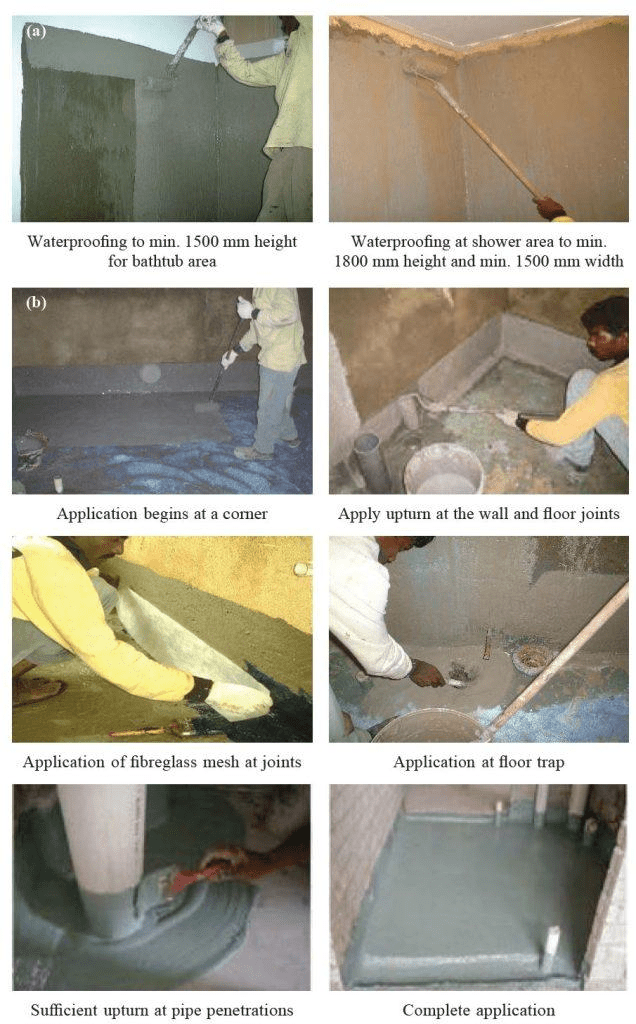
The membrane should be dressed up at pipe penetrations and down at least 50 mm into the floor outlet. Use of reinforcing fibreglass mesh along with the upstand is a better solution. The membrane should
extend horizontally around the pipe by min. 100 mm and overlap with subsequent membrane applied to
the entire floor in accordance with SS 637 or equivalent. A PVC flange should be bonded to the flooring and the PVC waste pipes before other fixtures (e.g., grates) are fitted in accordance with AS 3740 or
equivalent. Pipe sleeve with a puddle flange should be used to seal around the outside of pipes that are recommended to penetrate through the concrete floor.
Waterproofing
Design
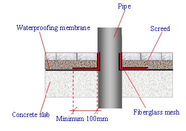
Proper design details of waterproofing membrane at pipe penetration should be provided as in the Figure 1 [1-2].

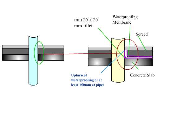
Alternatively, a water plug can be designed to cast around the pipe as shown. This water plug would work synergistically with the waterproofing material to enhance water tightness around the penetrations (Figure 2).
Material
A suitable waterproofing system should be selected based on lifetime performance of the system.
In general, waterproofing system applied at penetrations should be able:
- Suitable to its micro-environment conditions such as ventilation and surface dampness
- Easy to apply, especially at pipe penetration areas
- Be elastic and able to bridge over cold joints and differing materials
- Have good adhesion and cohesion strengths
- Able to retain its adhesion and remain stable under extreme fluctuations of temperature
- Able to resist mechanical damage such as peeling, cracking and rupture prior to screed finish
- Fully bonded to the substrate so that any leakage may be localized.
Construction
- The area to be waterproofed must be cordoned off. All pipes and floor openings must be fitted with temporary caps so that debris cannot enter and cause it to choke.
- Pipe penetrations are dressed up to the minimum height of screed level.

- Brush application of membrane is more suitable at pipe penetrations to ensure good coverage.
Quality Control
- Substrates should be inspected and prepared in accordance to the manufacturer’s recommendations prior to the execution of the waterproofing system.
- Waterproofing products should be sealed and delivered in original packaging. All materials should be protected from the weather and stored in a dry and secure place.
- Greater supervision during construction and a skilled labour force are important so as to control and improve the workmanship quality of a product.
- Checklists for the inspection of waterproofing work can be used as means to inspect the onsite workmanship quality. A continual check should be made on the amount of material that has been used and the area covered to ensure that the recommended coverage rate is being achieved.
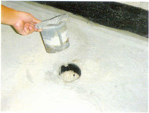
- The membrane should be tested for water-tightness after completion of the application. Make sure the membrane has cured properly before carrying on the test (Table 1).
| System | Time |
| Rubber-based systems | 1 hr to 72 hrs |
| Acrylic-based systems | 48 hrs for total system |
| Polyurethane systems | 24 hrs to 72 hrs |
| Cementitious systems | 1hr to 2hrs and flood test within 24 hrs |
Table 1: Curing Time
Plumbing
Design

It is a good practice to have minimal number of penetrations (Table 2) to minimize the inhomogeneity of the waterproofing membrane. Designing a common stack, the number of penetrations can be minimized (Figure 3).
| Fittings | Recommended number of penetrations |
| Urinal/WC | 1 trap shall be provided to serve a maximum of 10 urinals. For more than 10 urinals, more than one trap shall be provided. |
| Washbasin | 1 washbasin trap shall be provided to serve a maximum of 10 washbasins. For more than 10 washbasins, more than one trap shall be provided. |
| Wash/shower/bath | 1 floor trap for every 3 WC cubicles provided that the separating wall/ partition does not touch the floor level and the other 2 WC cubicles are graded to fall towards the floor trap (FT) in the third WC cubicle. |
Table 2: Recommended number of penetrations for different sanitary fittings
When the numbers of wet walls – 1 (minimum), the plumbing details are simple. Therefore,
- The discontinuities may be minimum, reducing the risk of water leakages
- Maintenance of the system may be easy due to the simple layout
Construction
The following guidelines can be followed during constructions

- Pipes and pipe sleeves should be cast with the floor slab rather than leaving openings or hacking after concrete has cured, to minimize water leakage caused by porous concrete around it.
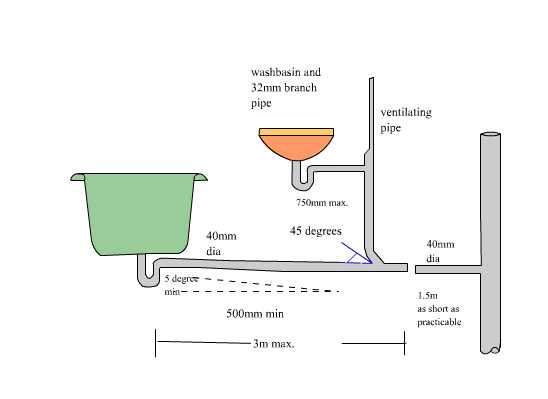
- Fixing of pipes with uniform and adequate gradients and specified lengths according to design so that they will drain efficiently [3-5] (Figure 4).

- Fix the pipes according to the relevant allowances for movement, providing either sliding supports for locations or rigid fixing for clamping at intervals given in Figure 5.
- Fix supports not exceeding the maximum spacing given in the table to minimise the risk of damaging the pipes (Table 3) [4-5].
| Maximum distance between sanitary pipe supports | |||
| Pipe material | Pipe size (mm) | Vertical pipes (m) | Low gradient pipes (m) |
| Plastic pipes | 32 – 405075 – 100150 | 1.21.21.81.8 | 0.50.60.91.2 |
| Cast iron | all sizes | 3.0 | 3.0 |
Table 3: Distance between pipe supports
- Remove any burs and swarf and ensure pipe bores are clean before jointing when the pipe is cut. Cut pipe ends square.
- Do not bend plastic or galvanized pipes during installation.
Ensure there are no congestions around pipes for easy pouring and vibration of concrete. Additional reinforcement is recommended to counteract the concentration of shrinkage stress, especially at corners
of openings, in accordance with BS 8102 and SS 637 (formerly CP 82) or other relevant and equivalent
standards. Conduits should be made in order not to allow water leaks in the basement. (SS 652: A.6.2)
The application of any membrane should begin at a corner diagonal to the entrance and upturns at wall floor junctions to avoid stepping on the applied area. Rollers or brushes can be used for the application
of the membrane in most locations. Rollers with the same width as the upturn could achieve an even and uniform application. However, critical locations where pipe penetrations and wall joints exist should be waterproofed using a brush to ensure good coverage