| Defects |
Probable causes for the defect |
Design for Maintainability (DfM) Guidelines |
| Short circuit
 Short circuit due to damaged/ impaired safety)
|
- Poor design details of busbars or cables: center line spacing, size, strength and provision of mechanical supports.
- No / faulty protective device.
|
Design
- Comply with the requirements of electrical installations as per BS 7671:2008+A3:2015, SS CP 5:1998, NFPA 70 [5]; including the location and number of power points.
- Ensure switchboards have adequate space and access for operation and maintenance.
- Specify suitable switch closets with regard to moisture exposure conditions.
- Refer to the definition of types and functionality of RCCBs and specifications for RCBOs as per SS 480:2016 (IEC 61009-1:2010+AMD1:2012+AMD2:2013 CSV BS EN 61009-2-1:1995).
- Provide sub-metering system with remote measurement capability and link to BMS/EMS to track energy consumption data trends [6].
Construction
- Conform to the guidelines for construction and compliance inspection of electrical connections and earthing thereof (BS 1363-4:2016, SS 403:2013).
- Refer to BS 8512:2008 for storage, handling and installation of power cables on wooden drums.
- Install sub-metering system with remote measurement capability and link to BMS/EMS to track energy consumption data trends [6].
- All accessible metal parts of connection units should be in electrical contact with the earthing terminal(s) (BS 1363-4:2016, SS 403:2013).
Maintenance
- Conform to the maintenance of electrical installations as per BS 6423:2014, BS 6626:2010, SS 538: 2008, [3;7].
- Check for insulation damages (e.g. cracks, blisters, warping) caused by overheating, physical impact or by spillage of cleaning chemicals.
- Check for potential short circuits or ground faults. Ensure that switchboards are not exposed to direct sunlight or alternative heat sources.
- Conduct annual shutdown to eradicate hot spots along the distribution network as witnessed by the owner and certified by a Licensed Electrical Worker (LEW).
- Provide necessary warning notices/labels at switchboards (e.g. shock hazard warnings).
|
Total power cut from one fault
 damaged wire bus
|
- Wrong / no provision of circuit breaker at desired isolation.
- Ballasts if not fitted with in-line fuse-holder and time delay fuse, one failed unit causes black-out in entire area.
|
| Difficult identification / rectification of defect |
- Haphazard wiring and wrong colour coding. Cramped wires in undersized junction box or outlet box also results in haphazard wiring.
- No ‘as built’ drawing available esp. for changes made by tenants. Distribution boards (DB) should also be preferably labelled.
- Inadequate number of intermediate pull or junction box.
- Difficult pulling over sharp bends in conduit. Long distance between junction boxes makes it difficult to replace any damaged wire.
|
| Poor performance of equipment |
- Poor insulation or inadequate conductor spacing causes impedance.
- Current supplied at lower than rated – poor planning or wrong tap adjustment of transformer.
- Voltage drop during starting of big motors causes momentary poor performance. Supply is of under capacity or not divided into sections.
- Voltage drop in undersized conductors.
- Wrong wiring connection at receptacles causes different voltage.
- Rating mismatch of equipment and supply.
|
| Nuisance tripping |
- Supply is far away from load centre of building and overloading at one part of the building occurs.
- Fuse of wrong rating or non-calibrated circuit breaker (CB) –usually from careless maintenance (Love, 2001).
- Transformer tap setting at lower standard may hike load.
- Loose connections causing spark, overheating or burning.
- Single phase circuit catering three phase equipment.
- Under-capacity of circuit to cater appliances with higher load factor.
|
Shock & electrocution
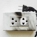 Burnt electrical outlet |
- Wrong polarity (e.g. switch gear connected to neutral). This may give shock even when the equipment is switched off.
- Deterioration of protective coverings / insulation with time or carbonization due to high voltage diff across insulation.
- Condensation on exposed live part. This happens if other services cross through electrical room or closet.
- Improper grounding or ‘mis-wiring’.
- Faulty/ no GFCI. Accidentally if any metal tool or ladder bridges the gap between two conductors, current flows through an unintended part of the circuit.
- No / poor connectivity of grounding system to clear the fault (H38).
|
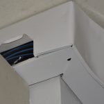
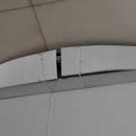
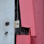
Arc, spark
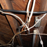 Exposed wire & loose connection |
- Damaged / charred insulation by careless splicing, mechanical impact, use of wrong cleaning chemical, exposure to high sources or aging.
- Connectors loose or have inadequate tip pressure, non removal of oxide, rusting etc.
- Bridging two exposed conductors by metallic tool. Places under regular O&M should not have exposed cabling.
- Very high resistance at connections if conductors are clamped together without sufficient contact pressure, corrosion of contactor or use of dissimilar material with different thermal expansion.
- Mechanical failure (creep) with time.
- Water enters through poorly detailed / finished transition points and corrodes conductor.
- Short circuit heating in undersized conductor.
|
References
[1]
Normative References/Standards Referred to for Air Handling Unit and Fan Coil Unit