Thermal and Infrared
The objectives of this category of tests are to identify bonding, composition, emissivity, heat contours, plating thickness, porosity, reflectivity, stress, thermal conductivity, thickness including detection of voids.
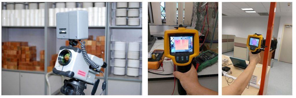
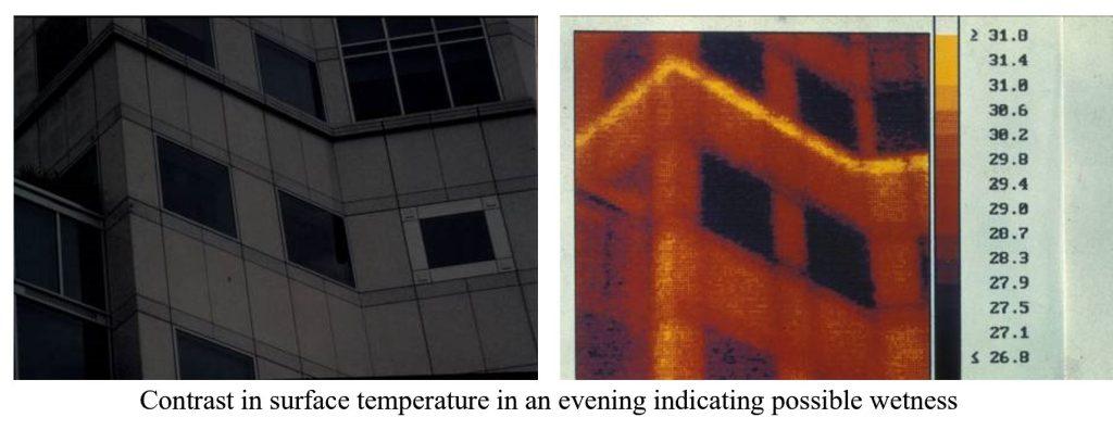
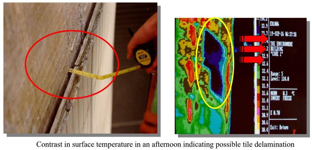
An infrared scanning camera is used to detect variations in the infrared radiation output of a surface. Thermal gradients along the surface of a material arise because of the difference in surface temperature due to variation in moisture content, existence of cracks, delamination, electrical piping, etc..
Infrared thermography utilises infrared detectors and optics to gather the infrared energy. It produces an output in the form of a thermal map known as a thermogram.
The thermal image can be videotaped or stored on a storage disk to be analysed later. Costly heat-related problems caused by a component or material failure, poor design in building components, and mechanical and electrical systems can be pinpointed.
Most modern thermal imaging instruments employ high-speed optics to scan the target point by point. They collect infrared radiation emanating from a target and direct it into a super cooled photo detector. The detector converts this incoming energy into a proportionate electric signal, which is then amplified. This amplified signal is then sent to a video processor and cathode ray tube (CRT), where it can be manipulated in a variety of ways for interpretive purposes. The image displayed on the face of the CRT is a temperature map in which variations in image density correspond to radiant energy differences in the original subject.
It is commonly used in building diagnostics of:
– leakage — moisture/electrical/air
– crack and delamination of claddings
– location of underground water/sewage pipes and defects
– detection of energy loss in buildings
– detection of reinforcement bars