Ground Penetrating Radar/Impulse Radar
Principle
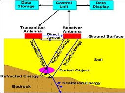
It is a high frequency testing technique which generates data by the propagation and reflected energy of radar waves (Electromagnetic waves).
The radar waves emitted by the antenna of the equipment are directed into the test material. The waves propagate through the material at a velocity defined by the electrical properties of the material. When a boundary of different electrical characteristics is encountered, part of the incident energy is reflected from the surface and the remainder travels across the boundary.
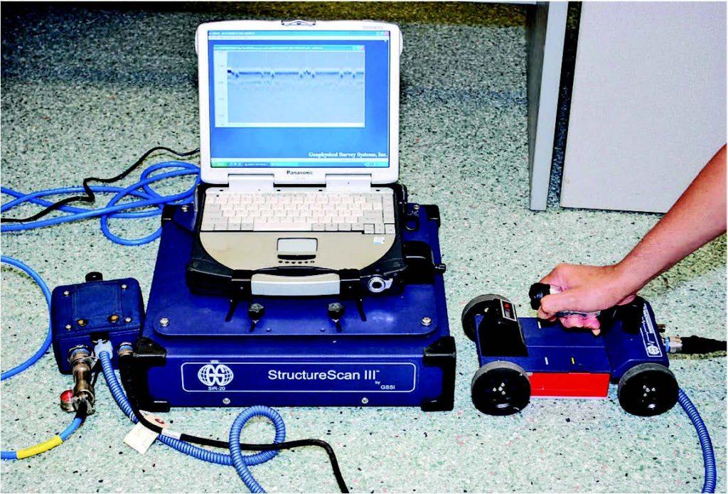
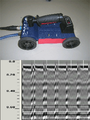
The reflected (echo) wave is picked up by the receiver built into the antenna. The antenna is swept over the test surface and forms a continuous profile of the material condition.
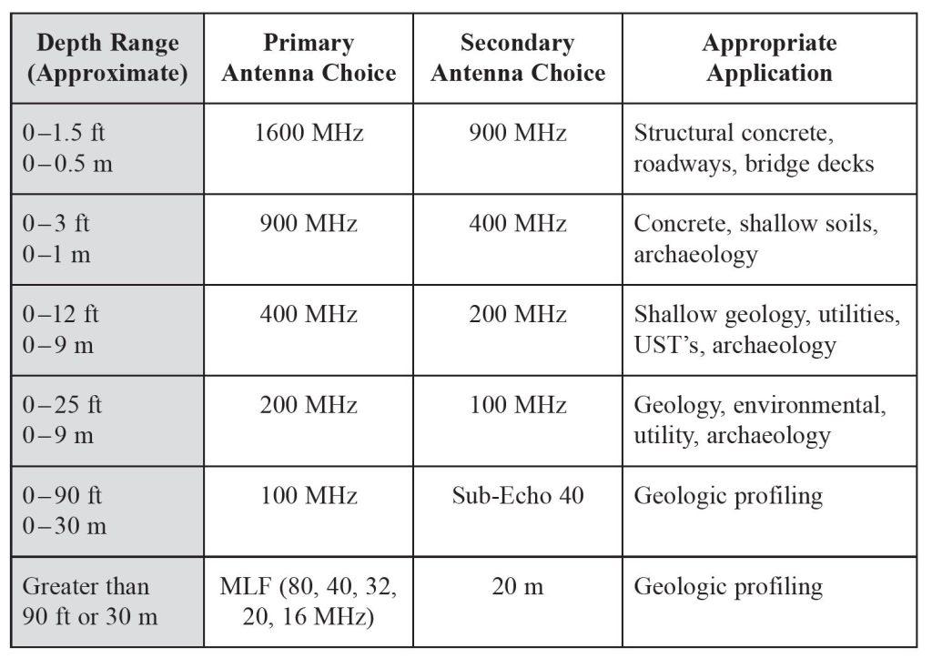
Antenna frequency is a major factor in depth penetration. The higher the frequency of the antenna, the shallower into the ground it will penetrate. A higher frequency antenna will also “see” smaller targets. Antenna choice is one of the most important factors in survey design (see Table below). Table 9.2 shows antenna frequency, approximate depth penetration and appropriate application.
Materials with a high dielectric are very conductive and thus attenuate the signal rapidly. Water saturation dramatically raises the dielectric of a material, so a survey area should be carefully inspected for signs of water penetration. Radar surveys should never be conducted through standing water, no matter how shallow it is. Depth penetration through a material with a high dielectric will not be very good.
Metals are considered to be complete reflectors and do not allow any amount of signal to pass through. Materials beneath a metal sheet, fine metal mesh or pan decking will not be visible.
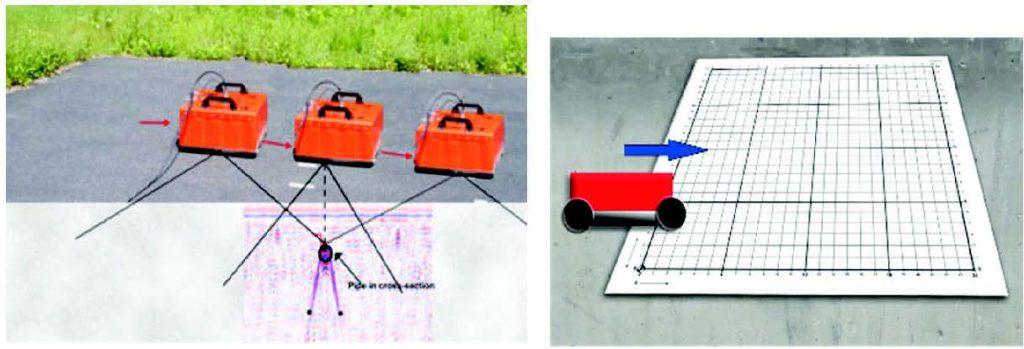
Radar energy is not emitted from the antenna in a straight line. It is emitted in a cone shape (Fig. 9.27). The two-way travel time for energy at the leading edge of the cone is longer than for energy directly beneath the antenna. This is because the leading edge of the cone represents the hypotenuse of a right-angled triangle.
Because it takes longer for that energy to be received, it is recorded farther down in the profile. As the antenna is moved over a target, the distance between them decreases until the antenna is over the target and increases as the antenna is moved away. It is for this reason that a single target will appear in a data as a hyperbola, or inverted “U”. The target is actually at the peak amplitude of the positive wavelet.
GPR can have applications in a variety of media, including rock, soil, ice, fresh water, pavements and structures. In the right conditions, practitioners can use GPR to detect subsurface objects, changes in material properties, and voids and cracks.
