The efficiency of a detector system is measured by its promptness to detect and fire or smoke and convey the message, but a highly sensitive detector may generate frequent false alarms. Hence selection is mainly guided by: (1) the required speed of response; (2) the expected nature of fire and (3) the sensitivity of detector to distinguish between such fire and normal environment.
The function of fire alarms may vary from basic duty to alert the occupants to evacuate but it may be highly sophisticated as activation of sprinkler, homing of elevators or notify the fire brigade. The design suiting to particular building requirements can be according to NFPA 72 or similar approved codes.
|
Defects
|
Probable causes for the defect
|
Design for Maintainability (DfM) Guidelines
|
Under performance or false alarm of detector/ faulty fire alarm panel
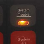 Fire alarm system fault indicated in fire panel. A faulty fire panel can cause fire incidents to go unmonitored 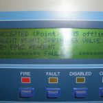 Control panel displaying fault message and indicating that detectors are offline |
- Flame detector is misaligned, damaged by shock (loosely fitted).
- Wrong selection (exposed to usual but high heat / smoke / light source).
- Function should be checked through simulation test after installation and during regular maintenance.
- Obstructed, covered by paint– poor housekeeping.
- Dirty – especially for poorly accessible points.
|
Design
- Design system to accommodate false alarm management as per SS CP 10:2005 and Fire Code [8].
- Locate fire alarm panel in corrosion resistant cabinet without any exposure to excessive dampness. Fire panel connectivity should be independent and compatible with the building automation system (BAS).
- Specify red wiring for fire alarm system. Segregate from other ELV cables to remove electromagnetic interference.
- Use alarm verification features to reduce incidence of false alarms.
Construction
- Installer should identify circumstances that can lead to a high rate of false alarms and should inform both the designer and user.
- Check to ensure acceptable levels of false alarms during commissioning (SS CP 10:2005, BS 5839-1:2017, BS 5839-6:2013).
- Install neatly and protect with sleeve as per manufacturer’s requirements (care to be taken in concealed spaces).
- For the protection of joints in junction box, refer to minimum joint requirements.
Maintenance
- Conduct regular testing and inspection of fire alarm panel as per SS CP 10:2005, BS 5839-1:2017, BS 5839-6:2013.
- Conduct daily check to ensure normal operation, and to record and rectify any faults. Perform weekly tests to check battery and voltage conditions.
- Conduct monthly simulation of zonal fire and fault conditions. Clean fire alarm panel for proper operation and visibility (NFPA 72:2016).
- Keep fire panels safe and secure from unauthorised tampering.
|
Faulty manual call point
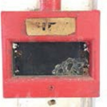 Dirty manual call point at an institutional building 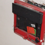 Damaged manual call point |
- No power supply (unreliable power source, faulty wiring or battery goes flat).
|
Design
- Designate locations of manual call points along all exit routes and at final exits (BS 5839-1:2017, BS 5839-6:2013).
- Manual call points should be located in such a way that a person should not have to travel more than 45m along an escape route to reach a manual call point, when the layout of the building is known. Each manual call point should be positioned 1.4m (+/-200mm) from floor level (BS 5839-1:2017).
Construction
- Use pull station type manual call points in outdoor areas rather than break glass type, in order to prevent water ingress.
- Ensure that manual call points are securely mounted and properly aligned (SS CP 10:2005).
- Upon installation, test the system (e.g. three- second response test for manual call point, battery removal test, etc.) (BS 5839-1:2017, BS 5839-6:2013).
Maintenance
- Conduct monthly test of manual call points on all alarm zones to ensure each part is functional, and especially check whether the remote auxiliary facilities are initiated or not.
- Monitor power supply and faulty wiring of call points and other elements of the fire detection system.
|
Inaudible or unidentifiable alarm1
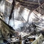 A site damaged by fire; fire propagated due to alarm system’s failure to signal in time |
- Wrong selection of bells –not distinguishable from general clutter.
- Loose gong bolt or damaged alarm – blocked, corroded, spoilt by extreme temperature fluctuation.
- Faulty alarm panel to indicate the exact alarm – no lucid diagram, corresponding bulb blown off or battery goes flat.
|
Design
- Design fire alarm system (e.g. location, type and number of alarms) as per SS CP 10:2005 (see also BS 5839-1:2017); and emergency voice communication system as per SS 546:2009 (see also BS 5839-9:2011).
- Alarm sound selected should be distinguishable from general clutter. Use a visual alarm where there is excessive background noise. Propose incident communication facilities (as per SS ISO 22313:2013) and determine internal/ external communication needs (e.g. through PA system integrated with iBMS) as per SS ISO 22301:2012.
Construction
- Establish, implement and maintain procedures for warning and communication (e.g. life safety); and set incident communication procedures (SS ISO 22313:2013).
- Link lifts with audible warnings and emergency detection system as per ISO/TR 25743:2010.
- Installation and cabling of fire alarm devices should be done in such a manner where, in the event of a fault, at least one sounder located within the vicinity of the control and indicating panel will remain in operation (BS 5839-1:2017).
Maintenance
- Inspect alarms for defects (e.g. loose or blocked gong bolt, damaged or corroded alarm, alarm spoilt by temperature fluctuations, etc.).
- Conduct annual check of all installed speakers, amplifiers, and connecting appliances (including cables) and keep records.
- Conduct routine check of fire alarm panel indicator bulb operation and battery (NFPA 72:2016).
- Perform real time monitoring and management of system performance.
|
Faulty fire detector
 Dirty and damaged fire detector 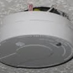
Faulty, corroded and improperly installed detector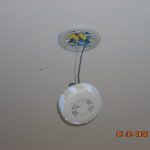 |
|
Design
- Comply with the fire detection system requirements of Fire Code 2013 by SCDF [8], SS CP 10:2005, ISO 7240 series, BS 5839-1:2017, BS 5839-6:2013.
- Ensure detectors are accessible for maintenance and replacement.
- Conform to the selection of heat, smoke, and flame types based on requirements on-location.
- For decisions regarding the number of fire detectors, and their location and spacing design requirements, refer to SS 575:2012, BS 9990:2015.
Construction
- Ensure the proper fitting of each fire detector, to avoid misalignment or damage caused by shock.
- Ensure quality workmanship so as to avoid detector obstruction and or detector being covered by paint.
- Remove paint, dust or any foreign material that can affect its function from detector.
Maintenance
- Practice proper housekeeping to maintain cleanliness and avoid obstructions (especially at poorly accessible points).
- Inspect fire detectors weekly, and conduct monthly fire alarm simulations from a randomly selected detector to check the entire system.
- Perform annual test of 20% of all detectors; all detectors will be inspected over a five-year period (SS CP 10:2005, BS 5839-1:2017, BS 5839-6:2013).
|
Malfunctioning or damaged backup power/lighting
 Damaged exit signage; may interfere with egress during evacuation 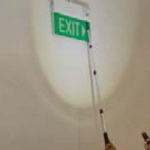 Good practice: Regularly test emergency exit signs to ensure that they are in working order |
|
Design
- Design emergency power supply systems in buildings as per SS 563-2:2010; and emergency lighting fixtures as per SS 563-1:2010 (see also BS 5266-1:2016, BS EN 50172:2004, BS 5266-8:2004, NFPA 101, AS 2293 SET:2005).
- Building emergency generator supply should be able to back up the emergency voice communication system (SS 546:2009, BS 5839-9:2011).
- A standby generator may be used solely to provide power to emergency lighting systems, or in addition, to meet requirements other than those directly associated with emergency lighting.
Construction
- Conform to the requirements for the installation of emergency power supply systems in buildings as per SS 563-2:2010, BS EN 1838:2013, BS 5266-1:2016.
- Individual luminaires should be mounted to avoid glare and if possible, should be positioned at least 2m above floor level (measured from floor to the underside of the luminaires).
- The horizontal illuminance on the centre line of any exit cannot be less than 0.5 lux. A fuel supply must be readily available to ensure that emergency lighting operates continuously for the rated period following the failure of normal power supply (SS 563-2: 2010).
Maintenance
- Ensure the maintenance of emergency power supply systems in buildings. Conduct a monthly manual test of emergency lights and replace batteries or lamps as soon as a fault is detected (SS 563-2:2010, AS/NZS 2293.2:1995/AMDT 3:2012).
- Conduct monthly fire simulation test. Simulate failure of main power supply and test the efficiency of the standby battery.
- Ensure visual and audible fault signals are activated once the battery is disconnected.
|
Alarm panel – no signal, spoilt exterior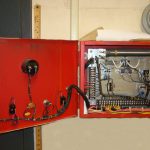
Obsolete alarm panel
|
- Proper connectivity to response centre is not provided.
- Panel is tampered – lack of concern for safety or unsafe location.
- Bulbs, buzzer etc can’t work if not reliable or battery goes flat.
- Bulbs blown off – not replaced.
- Exposed to excessive damp location, poor make corrode cabinet.
|
Design
Construction
Maintenance
|
1 The installed alarm system should emit a minimum sound level of 65dB(A) or dB(A) above back- ground noise (if lasting more than 30 secs) and at a frequency between 500Hz and 1000Hz. The maxi- mum sound level should not exceed 120dB(A). If the sound needs be carried through a door it should be taken into consideration that the decibel loss occurring through doors is approximately -20dB(A) through a normal door, and approximately -30dB(A) through a fire door (BS 5839-1:2017).
References
[1]
Normative References/Standards Referred to for Air Handling Unit and Fan Coil Unit


