BIPV/PV

Introduction
Photovoltaics (PV)
Photovoltaics (PV) is a promising renewable energy technology to overcome the global energy crisis and to achieve sustainable building design, especially in the tropics. Recent shifts in PV technology towards higher efficiencies and lower costs increases the potential usage of PV in commercial and residential buildings1.
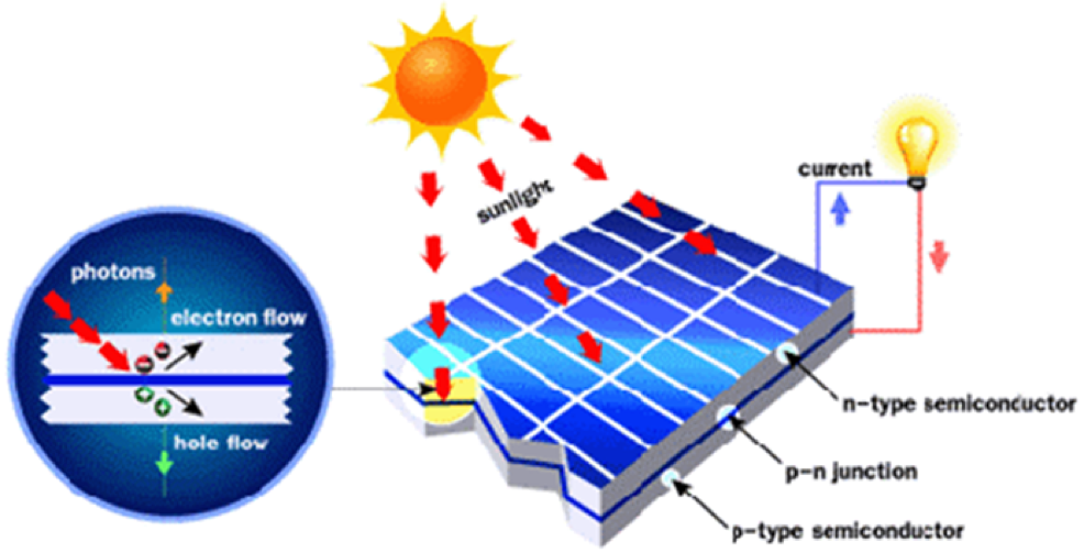
PV technology converts solar energy into direct current (DC) electricity using semiconducting materials based on photovoltaic effect using their physical and chemical effects which display voltage or electric current production upon exposure to light2.
Photovoltaics (PV) or solar cell technologies are traditionally divided into three generations by its material and working principles (Refer to Table 1 for a comparison of these difference technologies).
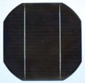
The first generation PV panels mainly constitute of crystalline silicon (multi/mono), also known as silicon wafer-based photovoltaics. These PV modules use a large-area, single layer p-n junction diode, which can generate electricity from a light source according to the wavelengths3.
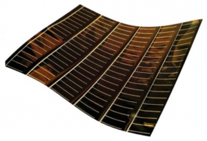
The second generation of photovoltaics depends on the use of semiconductors deposited in a thin-film and compared to the first generation, the second generation solar cells are less at risk to lose efficiency at higher temperature conditions (lower temperature coefficient). The primary materials used for these PV cells are Amorphous Silicon (a-Si), Cadmium Telluride (CdTe) and Copper Indium Gallium Diselenide (CIGS)4.
The third generation solar cells try to incorporate advantages of its predecessors and overcome the Shockley-Queisser efficiency limit (a theoretical limit for earlier generation PV cells)5. These PV modules can be made alternative materials, such as; nanotubes, silicon wires, solar inks, organic dyes and conductive plastics6.
| PV Generations | Examples | Advantages | Disadvantage |
| 1st generation | Si-Mono
 Si-Poly 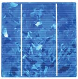
| Highest conversion efficiency (up to 30%)
Mature technology and wide market application | More energy and material consumption
High cost High temperature coefficient Rigid, appearance and aesthetical limitations Rely on the direct radiation |
| 2nd generation | Amorphous silicon
 CdTe 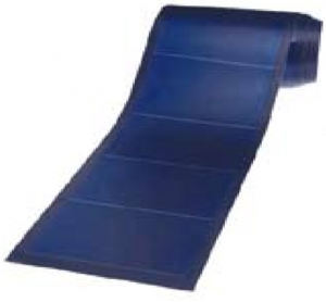 CIGS  | Moderate efficiency (8%~20%)
Thin, flexible Less material consumption than 1st generation Lower price in terms of $/watt of electrical output Less maintenance required (allows usage in inaccessible areas such as rooftop/façade) | May cause heavy metal pollution
May use rare elements Lower efficiency than silicon wafer-based PV cells |
| 3rd generation | Organic
Perovskite Dye Sensitised Solar Cells (DSSC) 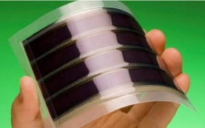
| Light weight, low cost
Thickness can be less than 1 µm High throughout roll-to-roll production Semi-transparent Easily integrated with different applications (highly dynamic) No thermodynamic limits Less expensive Efficient over a wider band of solar energy (e.g. including infrared) | Lowest efficiency (4% ~ 12%)
Low operational lifetime (6 – 21 year) Batch to batch variations in organic source material (for OPVs) Immature technology, still under lab research and not commercially available |
Table 1 Comparison of different PV/BIPV generations
There are various reasons when a PV does not generate much energy, this happens: 1) due to the shading effect contributed by the surrounding neighbourhood; 2) due to the decrease in the module peak power and related effects on the inverter power ratio (IPR); 3) due to failure of the maximum power tracking failure; 4) due to defective modules on the PV (Omer, Wilson, & Riffat, 2003) and 5) due to the amount of dust deposited on the PV, which also one of the factors that affect the PV efficiency (Karmouch & Hor, 2017). Dust accumulation is caused by high wind speed intensity, which results in a decrease in efficiency of the PV module (Goossens & Van Kerschaever, 1999). Another factor that affects the PV efficiency is the temperature. Once the temperature goes beyond the optimal efficiency, the amount of electricity generated reduces (Jelle & Breivik, 2012). With this condition, the cell type is also crucial since different cells have different levels of efficiency (Ng, 2014). The types of application for the PV is also crucial in maximising the PV performance (Wittkopf, Ang, Poh, & Pandey, 2008)(Chiang, 2008), as well as the sloping angle and orientation of the PV also affect its performance at different periods of the day (Khoo et al., 2014).
Safety Concerns on PV
In the early days, PV was known to be safe and dependable as they were used solely alone for charging batteries. However, as more research is being done and the solar cells increased in numbers, it has been found out that it can cause various safety hazards. When the cells are connected in series, they will produce the same amount of current with an increased amount of total potential difference. This may lead to overheating which can cause fire when there is a sectional or complete shading of the various cells connected in series. When a cell is shaded partially, the amount of current produced decreases thus acting as a reverse biased diode. While current is flowing in series, the total potential difference of the cell that has complete exposure can get applied to the shaded cell as reverse bias (Dhere & Shiradkar, 2012). Based on a research regarding PV fire hazard, the roof-integrated PV systems had a fire risk of 20 times greater than a normal stand-off mounted PV generator. This is because the buildings with a stand-off system are covered by a “hard roof” with the usage of tile that protects the building from external sources of fire. It was also advised that prudence in design and installation need to be practised and that special protection is needed for the important parts of the system (Laukamp et al., 2013).
In the event of fire at a facility, the firefighters will usually disconnect all utilities. However, it is difficult to do so with PV system inverter as it is able to hold a charge and send energy back up to the PV panels. Moreover, as long as there is sunlight or bright lights shining onto the PV panels, it will continue to produce electricity. Thus, the conduit that connects the PV panels to an inverter remains live with direct current after the main service panel is not working. In the midst of a fire, the high DC voltage and current can cause electric shocks to ct people. When the DC cable insulation melts, a DC flash arc occurs which caused an additional threat to the firefighters (Allianz Global Corporate & Specialty, 2012).
Another safety concern is the occurrence of an open circuit which is caused when the PV is not mounted or installed properly; due to moisture and corrosion; or even the occurrence of a crack. An open circuit is an electric arc that occurs between a small gap that will happen for a long duration when the two electrodes are permanently located at the same position. Lastly, the occurrence of an arc will lead to the development of a ground fault. In the event that there is a low resistance path to the ground; overheating, arcing and fire can occur. For instance, a corroded junction box can create a ground fault that will cause arcing, which will lead the arc to melt the glass if not noticed for a long period of time. The arc will produce the plasma at a high temperature and will act as a low impedance path. Once an arc occurs and fire will ignite after some time, it is hard to extinguish the fire when there is electricity flowing through (Köntges et al., 2014). There are three types of arcs: 1) serial arc occurs when the connection is pulled away while the PV produces current. This is common especially in loose connections or connector defects; 2) parallel arc occurs when the insulation system breaks down. The opposite polarity conductors in the same DC circuit will be in close distance. The insulation can fail if there is cracking, ingress of moisture or even a UV breakdown; and 3) ground arc occurs on the ground cables when there is only one insulation system in fault (Allianz Global Corporate & Specialty, 2012).
PV in the presence of fire and water
The hazard of an electric shock due to water is reliant on the distance between module and water, its the potential difference and spray pattern as well as the water conductivity. Salt water is not suitable for live electrical equipment, while foam or a pool of water may be energized when there is a damage in the PV system. Also, even if the disconnected switch opens, the solar system will still be working as long as the module receives light and the inverter has received direct current from the solar modules. This is something that makes the PV different from a normal electrical utility. At night when artificial light is received by the module, it may be illuminated, and it can produce electrical power to cause a hazard. When the array of modules is being damaged, new electrical circuit paths will be created. In the event that the modules are damaged, there may be fire and electric hazard, it can happen at the damaged area or other areas depending on the circuit path (Backstrom & Dini, 2012). in addition, there are instances where the solar panels have deterred fire fighters from fighting fire due to the following reasons: 1) the solar modules may obstruct the main areas and paths that the fire fighters will use; 2) the increase in weight will lead the roof to fall especially if the structure has been compromised; 3) as parts of the system will decompose, toxic fumes may be produced; and 4) there will be objects falling from the roof top or wall (Allianz Global Corporate & Specialty, 2012).
Building-integrated Photovoltaics (BIPV)
Building-integrated Photovoltaics (BIPV) is the integration of thin-film photovoltaics (PV) modules into the building envelope. BIPV uses individual solar cells which are interconnected and encapsulated on various materials to form a module. These PV modules are modeled in such a way that it replaces the conventional building envelope materials. At the same time, it also helps in generating renewable energy for the building’s consumption7.
Integrating PV systems with the building envelope brings potential benefits over power generation as it also provides shading, which can reduce the building cooling load. Mainly there are two kinds of PV systems fixed on buildings; BIPV (Building-integrated PV) is when PV panels are integrated into roof or façade of a building as a part of the structure, and BAPV (Building Applied PV) are when PV panels are added to the building after construction. Comparing to BAPV (or rack-mounted PV system), BIPV replaces conventional building materials and hence is more cost effective and aesthetically pleasing.
Components of BIPV
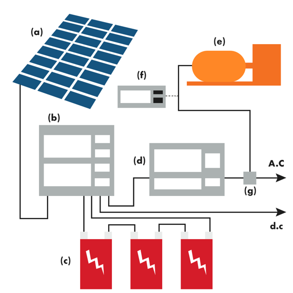
As illustrated in Figure 3, a complete BIPV system includes several components and they are:
- Thin-film or crystalline PV modules which can be transparent, semi-transparent or opaque
- A charge controller to regulate the power inflow and outflow of battery storage bank
- A power storage system which comprises of utility grid
- Power conversion (i.e. inverter) to convert the DC output from PV modules to AC compatible with utility grid
- Backup power supply (i.e. diesel generators) in case the system fails to operate
- Appropriate support and mounting hardware, wirings and safety disconnects
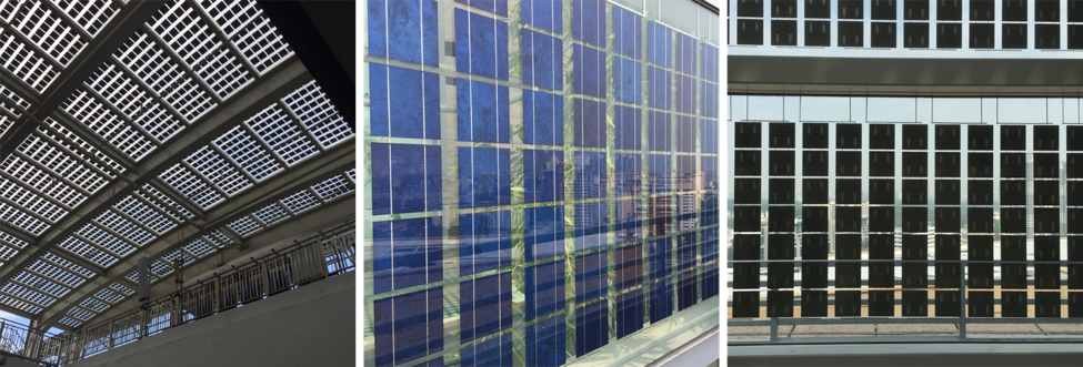
Different types of BIPV – PV cells in the glass
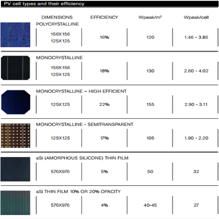
There are various types of PV cells choices for BIPV that are available in the market. However, the efficiencies for the different BIPV would differ based on the types of PV cells. As depicted in the figure above, we can see that the first four crystalline materials are far more efficient than the last two types of thin films. The transparency of the PV cells would allow more daylight into the building space; however, the efficiency would be compromised. BIPV systems can also be categorized according to its make, functions and characteristics8;
- In-roof systems;
- Solar tiles;
- Cladding systems;
- Semitransparent systems;
- Shingles flexible laminates.
Solar energy is one of the renewable energy resources that can be easily obtained. Moreover, solar energy is inexhaustible and has no pollutant problems. On the state-of-the-art of photovoltaic (PV) systems development, building incorporated photovoltaic (BIPV) has become the most promising and potent technology. Compared with traditional non-integrated PV systems, BIPV does not require any no extra allocation place, brackets, or rails for installation, and at the same time also offers instantaneously electrical power for buildings such as indoor air-conditioning and illumination9. Studies have revealed that BIPV system is able to decrease the cooling load and electric consumption of a building by 33–50%10.
Today, building-integrated photovoltaic is being considered by building designers as an innovative technique for clean energy production and reduction of greenhouse gases14 . BIPV technology is widely implemented to new and retrofitted building, constituting as a primary source of electricity9. It is a multi-functional technology with the usability of building materials and may represent as both a powerful and versatile tool for achieving the trend towards zero energy and zero emission buildings of the near future8. As BIPV are photovoltaic materials replaced over conventional building materials via the integration to different parts of the building components such as roof, skylights, or facade11, they are able to reduce the heat transmission through it12. Moreover, integration of photovoltaic modules to the building would allow the efficient use of space and production of energy. The application of BIPV enables photovoltaic modules to be used in different parts of the construction such as roof level (solar tiles) and absorb more incident solar radiation and thus reducing heat loads on the building. Photovoltaic modules are also used commonly in external facades to replace traditional glass and allow a decoration active in the energy saving. The daylighting of the building can be developed and specific design of the PV modules (BIPV) adapted to lighting needs of the day can be obtained by adjusting the spacing between solar cell assemblies in the case of silicon technology13.
Benefits of BIPV
There are various benefits that the BIPV can bring as compared to a PV Panel. BIPV is more aesthetically pleasing when installed on a building as compared to PV panels as it has a consistent look and blends in well as a design. BIPV is suitable for places that require preservation of its original characteristics and it can act multi-functionally by being weather resistant to its surroundings (GSES,2016). Biyik et al. (2017) have reviewed that when BIPV is designed properly, the thermal envelop can achieve 15 to 35% of savings in energy. Moreover, heat recovery applications can be implemented in combination with envelope solutions as thermal envelope benefit which are affected by the design and PV glass configuration. BIPV can provide good sound insulation as it’s behaviour is similar to the glass facades that are used conventionally. It is also easy to install with easy structural and mounting system made up of aluminium staples, brackets and profiles.
Challenges in BIPV adoption
Despite the promotion of the usage of BIPV, there are still some considerations (i.e. legal and administrative, PV market, technicalities and perceptions) that the various stakeholders must implement. It was found out that the people perceived BIPV to be strange when integrated as part of a building and they think that it is more cost effective to implement a solar thermal system than a photovoltaic system. Also, the solar modules require big spaces to install which are not always available and that the most optimal orientation might be hard to achieve. (Salem & Kinab, 2015a). There are also technical barriers which refer to the structural problems when construction professionals like engineers, architects and installers faced when they design and install the solar systems to the building envelope. A PV system has many interconnected modules and attached to numerous inverters to produce electricity. These modules need to be placed in strategic areas that are not shaded and not in the South direction. In addition, the structural integrity of the building needs to be considered as some roofs may not have the strength to support more weight onto the building. Also, there is a lack of awareness of consumption of electrical energy to define the value of the building, thus not all building stakeholders are receptive to the idea of BIPV in the building. This is because some building owners do not see the value of using BIPV as an alternative source of energy (Ikedi et al., 2010).
BIPV is costlier compared to PV panels as the technology of it is more complex such as the cost for an amorphous type of BIPV is $2.01 per watts which is much higher than the normal façade glass36. In addition, high installation cost ($2.00-$3.00/) may also further extend the payback period36. These are possible reasons that may hinder the developers and owners to consider the BIPV as part of building façade. In the other hand, the high cost of BIPV is due to small market in Singapore, few owners want to install BIPV as building façade and thus, causing supplier to import the BIPV panels from overseas. High transportation cost would further increase the cost of BIPV. Another challenge is that some architects feel that BIPV compromises the aesthetics of the building.
There are multiple considerations that BIPV businesses need to know ranging from the planning, design and implementation of the system. Each BIPV project needs to involve the different trades like electricians, roofers, cladding specialists, engineers, architects. Since the BIPV act as a façade, it has more contact with the surfaces of the building and hence less airflow which may lower the performance of PV modules due to higher temperatures (GSES, 2016). Therefore, it is also important to address to the main stakeholders (e.g. architects and builders) with different perspectives and convince them of the cost savings that will be reaped by the BIPV (EPIA, WIP, FIEC, AIE, 2008). Since BIPV provides renewable energy, this will be a great selling point to the Singapore government, as it strives to be a green and self-sufficient city. Financial subsidies and support from the local government and other relevant authorities will hasten adoption of BIPV and help lower BIPV implementation costs.
Codes and Standards for BIPV
Globaly, there is no uniform standard for all BIPV applications (Ikedi et al., 2010), thus it is necessary that building developers, engineers, architects, panel manufacturers and installers must have an active discussions in relation to the total integration of PV module to avoid any potential problems with leaks, dampness and insulation that may occur (EPIA, WIP, FIEC, AIE, 2008). The installation of BIPV includes installing the modules into building envelope and connecting the electrical components together and that all these need to adhere to the various building codes and electrical standards. It needs to ensure fire safety so that when the electrical components are faulty, there will not be an occurrence of fire (GSES, 2016). In terms of fire safety, good labelling, fire management, usage of correct fuses, good pathways leading to the modules and proper installations are essential for the fire safety of the BIPV. Areas with PV should have smoke ventilation opportunities and have an emergency egress especially for roof PV (Brooks & Engineering, n.d.).
The SS CP5 (Code of Practice for Electrical Installations) has provided some requirements for the installation of PV system installations. There are codes for protective measures such as automatic disconnection of supply, double or reinforced insulation, prevention of overload on the D.C side, installing an over-current protective device, to have small area for wiring loops, the PV array junction box, PV generator junction box and switch gear assemblies should be following IEC 60439-1, the PVs also need to have enough heat dissipation when exposed to maximum solar radiation at site, requirements to ensure safe maintenance. For modules with Silicon crystalline cells, IEC 61215 is used, while for thin film cells, IEC 61646 is used (Dougherty, n.d.).