Case 3
- Introduction
- Causes of Defects
- Good Practices
- Standards
- Maintenance and Diagnostics
- Remedial
- Similar Cases
- References
Good Practices
Design
Design to accommodate differential movements of the structure and provide movement joints to mitigate differential settlement or shrinkage of cracks. Recommended minimum wall joint width of 3 mm
(5 mm preferred) and minimum floor joint width of 5 mm. Spacing of movement joints on the internal
wall should be 5 m to 6 m horizontally and vertically, while space for the internal floor should be 6 m to 7 m in all directions in accordance with BS 5385-1, SS 665 or equivalent. Specification of less water-permeable tiles for wet areas. Recommend testing of tiles against design specifications before mass installation in accordance with ISO 10545-1 or equivalent. Cracks at tile joints are commonly due to the settling process, and thus requires pointing in accordance with BS 5385-3 or equivalent.
Construction
Tile fixing method should be guided in accordance with SS 665, BS 5385-1, BS 8000-11 or equivalent,
including:
-Tiles should be cut and handled with care during application;
-Tiles should be soaked to relieve their dry condition before laying;
-Screed should be properly cured, rendered and cleaned;
-Tiles should not be laid over cracks or be subjected to any loading; and
-Tiles should be properly tapped in place, and have their surfaces wiped after tiling.
Tiles should resist cracking from soaking or transverse elongation. They should be of a thickness adequate for resisting cracks from direct impact. Use a proper key at the back of the tiles for good bonding.
Waterproofing
Material
The decision to select a specific waterproofing system should take into consideration the design of the substrate structure and area of coverage. Due to wet area’s inherent nature of being small with many penetrations, protrusions and discontinuities, a flexible system is more suitable for internal wet areas.
In general, the selected waterproofing material should possess the following qualities:
- Suitable to its micro-environment conditions such as ventilation and surface dampness (Table 1)
- Compatible with the other subcomponents such as screed, tile bedding or even type of tiles (in a vertical surface) (Table 1)
- Easy to apply, especially at pipe penetration areas
- Be elastic and able to bridge over cold joints and differing materials
- Have good adhesion and cohesion strengths
- Able to retain its adhesion and remain stable under extreme fluctuations of temperature
- Able to resist mechanical damage such as peeling, cracking and rupture prior to screed finish
- Fully bonded to the substrate so that any leakage may be localized.
| Conditions | Justification |
| 1. Ventilation | Adequate ventilation is necessary for some systems to be cured adequately.
|
| 2. Surface finish (vertical) | System should be able to accommodate (wall) finishes
|
| 3. Surface dampness |
Therefore, in general, solvent based systems are not suitable while water based systems are suitable for damp surface conditions. |
| 4. Construction time | Systems that require long curing time is not suitable for limited construction time
|
Table 1: Characteristics of a waterproofing system
Waterproofing systems selected for use are required to be specified to relevant local building requirements or to International performance standards. These may include subjecting the materials to stringent tests to determine their performance under actual site conditions.
Construction
- Substrate preparation for application of waterproofing membrane is very important in this process to obtain excellence bonding. The following good practices can be carried out:
- Surface of the concrete slab should be checked for surface defects after casting. These defects should be removed and repaired to achieve the flatness for waterproofing. This is to ensure excellent bonding property between the substrate surface and membrane [1-2].
- When the surface has imperfections like honeycomb and defective concrete, it should be repaired or removed down to sound concrete and patched up with suitable mortar such as shrinkage compensated grout, polymer modified mortar, epoxy mortar etc.
- If the surface contains any greasy or oily contaminants, both chemical and mechanical cleaning can be used to remove them.
- Finally, surface should be cleaned to remove debris and dirt. Some cleaning methods include high-pressure water jet, cleaning with vacuum cleaner or with brooms. Excess water should be removed to provide dry surface for waterproofing application.
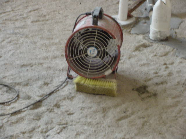
- Blowers can be used to dry the surface faster (Figure 4).
- Proper mixing of the liquid is important to make homogeneous paste before applying it.
Quality Control
- Substrates should be inspected and prepared in accordance to the manufacturer’s recommendations prior to the execution of the waterproofing system.
- Waterproofing products should be sealed and delivered in original packaging. All materials should be protected from the weather and stored in a dry secure place.
- Greater supervision during construction and a skilled labour force are important to control and improve the construction quality of a product.
- Checklists for the inspection of waterproofing work can be used as means to inspect the onsite workmanship quality. A continual check must be made on the amount of material that has been used and the area covered to ensure the recommended coverage rate is being achieved.
- The membrane should be tested for water-tightness after completion of the application. Make sure the membrane has cured properly before carrying on the test (Table 2).
| System | Time |
| Rubber-based systems | 1 hr to 72 hrs |
| Acrylic based systems | 48 hrs for total system |
| Polyurethane systems | 24 hrs to 72 hrs |
| Cementitious systems | 1hr to 2hrs and flood test within 24 hrs |
Table 2: Curing Time
Tiling
Construction
The render layer should be allowed to set and dry for at least 2 weeks before tiling work is due to start. This is important to reduce the potential of drying stress to minimize shrinkage cracks.
Prepacked mortar is preferred so as to achieve a consistently good mix and this would minimize many omissions, which leads to cracking and debonding, during construction.
Following precautions can be followed up to prevent cracking of tiles during the application:
- If the bedding material is ordinary cement mortar (Figure 6a), the surface (render) should be damped to prevent any suction of water from screed/render. However, if the bedding material is an adhesive (Figure 6b), the manufacturer’s instructions should strictly be followed. These instructions such as surface preparation, mixing and application of adhesives are clearly labeled on the packing.
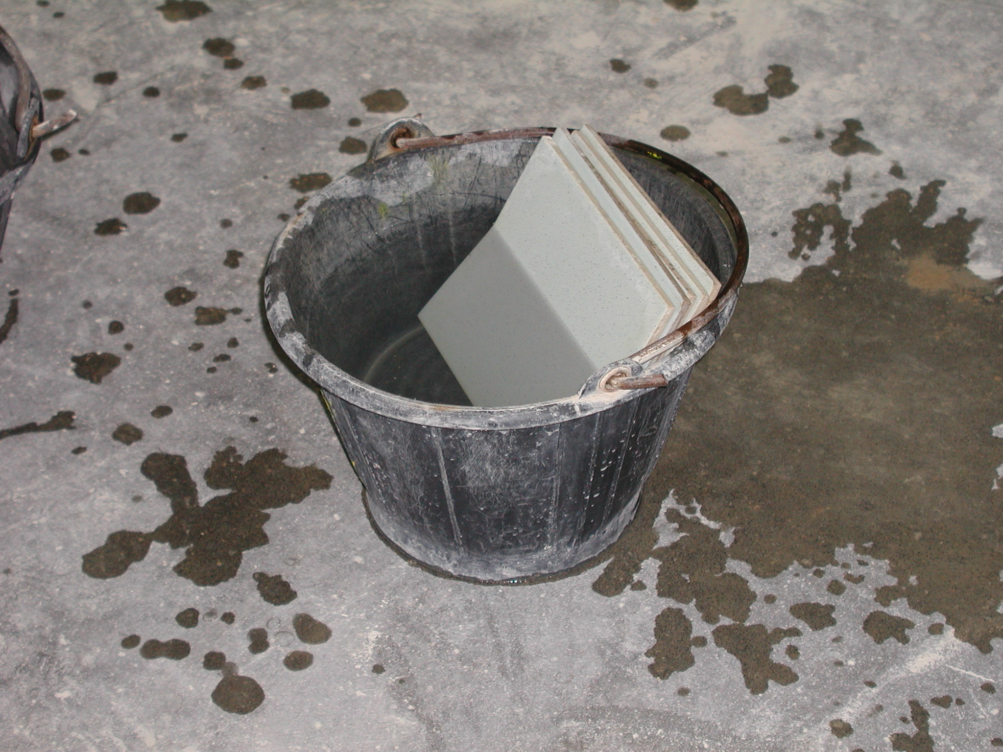
- If the bedding material is cement mortar, porous tiles should be soaked in clean water for 12 hours to surface-saturated-dry (SSD) condition to prevent excessive absorption of water from the render and then (Figure 7), kept vertically to drain off the excess water. This is important to prevent the tiles from drawing water from the cement mortar and to prevent shrinkage cracks from forming. However, glazed ceramic wall tiles should be tested to confirm that soaking would not lead to crazing.
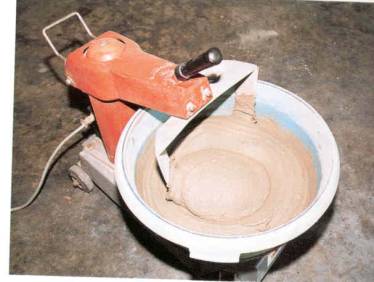
- The bedding mortar or adhesive should be mixed with a mechanical mixture to obtain a uniform mixture (Figure 9).
During the fixing, following good practices can be followed up to obtain good bonding [3-7],
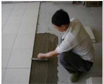
- The mortar should be applied to a consistent thickness of not more than 10 mm and do not spread adhesive over a coverage that could not be covered with tiles in time as the surface of adhesive may form a skin which prevents bonding. In general, the maximum spread should be limited to about 1 m2 (Figure 10). However, if the bedding material is an adhesive, “open time” of the adhesive film should be considered in this regard.
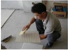
- The background of the tiles should be damp and clean when fixing with mortar (Figure 11). When tile adhesive is used, the background should be dry and clean.
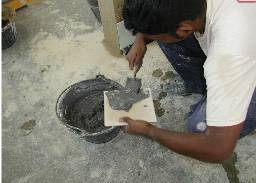
- Mortar or adhesive should be spread on the damp or cleaned background of the tile. The keys and frogs on the tile back should be completely filled up with mortar, with a thickness of not less than 2 mm but not more than 6 mm exceeding the depth of keys or frogs (Figure 12).
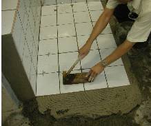
- The tiles should be then placed firmly with a twisting motion (don’t slide tiles in), ensuring regular and straight joints to a recommended width. Once they have been put in position, they should be uniformly tapped using a hammer into place to achieve good contact. A block should be used to prevent over-hammering that will chip or crack the tiles (Figure 13).
Quality Control
To check for complete adhesion behind tiles, random removal of tiles could be carried out as work proceeds (Figure 14) [8]. In general, adhesive must cover 90% of the back of any tile, which is randomly removed for checking. If this condition is satisfied, the adhesive is cautiously removed from the tile and the substrate, and re-applied with fresh adhesive. If this condition is not satisfied, other tiles in the vicinity of the original tile should be removed to check if the fault is general.
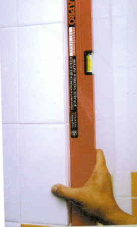
Tolerances for surface unevenness:
|  | 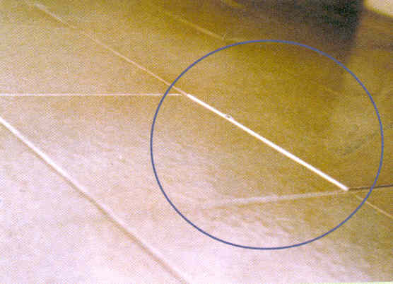 |
| Interface with other elements
Tile interface with ceiling, window frames, door frames, pipes etc are aligned and consistent | ||
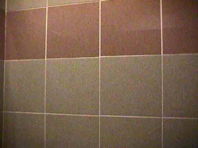
Joints, tonal variations:
| ||
 | ||
| Hollowness, chip offs, sharp edges and crack
Surface is free of chipped, cracked (Figure 11a)and hollow tiles (Figure 11b). | 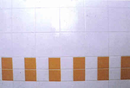 | 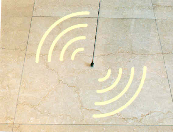 |
| In addition, a checklist for onsite tiling inspection can be used to control tiling work during construction. | ||
Source: BCA 2001 Good Industry Practice-Tiling[11], BS 5385-3:1995- Wall and floor tiling. Code of practice for the design and installation of ceramic floor tiles and mosaics in normal conditions